


Rigging Plan For Heavy Lifting
1. GENERAL
This procedure provides information for the erection of Steam Drum Boiler at Project.
2. PURPOSE
This Procedure is to make sure that all people involved in the erection, assembly and welding of Steam Drum activity understand and familiar to do the work with quality control system for getting quality result as per client specification and requirement, drawing, standard and code.
Download link given in the bottom
3. GENERAL NOTE
3.1. Inspection
As per the works required inspection, carry out inspection under attendance of Superintendent / Engineer and as surreally record is result.
3.2. Safety
- A safety officer presents all times Safety Briefing.
- Job Safety Analysis (JSA) must be carried out for all crane lifts and all other tasks that have potential risk to personnel of equipment.
- Install scaffolding where necessary to install bolt in each beam and member connection.
- Pre lift study before any lifting activity.
- Lift briefing and Safety briefing before any lift; assign responsibility to all personnel involved. (Signalman, Rigger to crane driver, etc.)
- Ensure all equipment required for installation is on hand and in position before lift i.e. Chain blocks, Lever blocks, Podgy, Drifts, Hammer, and Spanners. Etc.
- Tag lines must be used to control lift.
- Ground conditions must be ready before activities.
- Set up safety rope around lifting area of Steam Drum area and put notice board entered “KEEP OFF EXCEPT PERSONNEL CONCERNED”.
- Lifting equipment should be in certification and tagged.
- Crane and other machinery shall be inspected and certified.
3.3. Lifting
All conditions adapted to the lifting procedure. Prior to commencement of lifting works, assuredly carry out check of lifting equipment.
3.4. Assembly and erection
Erection steam drums accordance with the manuals and drawings.
4. RESPONSIBILITY
4.1. Chief Construction
Responsible for the overall planning, coordination and control of erection work.
4.2. Field Engineer
Responsible for field erection work implementation and maintaining acceptable quality standard.
4.3. Field Superintendent and Supervisor
Responsible for the actual performance of the erection crew and examine the actual progress of work to ensure that it fit the drawing, specifications and standards.
4.4. Quality Control Engineer
Responsible for monitor and inspect the erection activities to ensure it is being done in compliance with procedure, ITP (Inspection and Test Plant), drawing, Project specification and other reference standard document and procedures.
4.5. Supporter Activities
These activities will support by Material Control, Quality Control, Welding Section, and others section related with these activities.
5. BASIC REQUIREMENT
5.1. Schedule and Planning
Master schedule is usually provided by Main Contractor. The detailed schedule is prepared by Contractor according to his planning which is based on Main Contractor’s master schedule. The milestone and the critical path can be identified which require proper planning. The sequence of erection activities and the resources required is included in the planning.
5.2. Erection Drawing and Erection Manual
Erection drawing and manual usually provided by Vendor. The Field Engineer and Superintendent shall check all drawings intended for Steam Drum Erection. All the information required is completed and all drawings shall be of latest revision.
5.3. Packing List
Packing List shall be provided by Vendor. This included all the listing of materials, equipment and parts that are supplied.
The Packing List should indicate the quantity of the material and equipment supplied and its specification as described in the erection drawing. This will also indicate the size and the total weight of the component and the method of storage. Also the packing number and material coding is very essential.
5.4. Storage Area and Warehouse
Upon a thorough check on the drawing and the packing list, the quantity of materials and equipment is already known, including the method of storing, the size of the storage area and the warehouse can be identifying.
5.5. Resources
Identification of resources is integral part of planning and scheduling is the most essential part of the basic requirement in undertaking Structure Boiler in particular and in all jobs in general. Resources means, the materials, labour and equipment needed to perform Structure Boiler Project.
6. PREPARATION WORK
6.1. Checking of Steam Drum Erection Drawings
This has to be done by the Chief Construction, Field Engineer, Superintendent and Supervisor to determine the correct resources needed to perform the job.
6.2. Checking of Client Supplied Material and Equipment
Checking and inspection of the materials and equipment including the spare parts is to be done by the material control. He will make sure that all materials, equipment and spare parts received from Main Contractor, conform to the quantity and the specifications started in the packing list or shipping.
6.3. Checking of Erection Materials, Equipment, Tools and Machinery
In the early stage of planning, these resources had been already identified. The schedule of mobilization ason planed schedule made by the Chief Construction and Engineer.
6.4. Checking of Labour
Labour requirement for every stage of erection job is prepared by the Chief Engineer and his erection team, which is in accordance to their planning.
7. ORGANIZATION CHART

8. STEAM DRUM ERECTION SEQUENCE

8.1. REMARK:
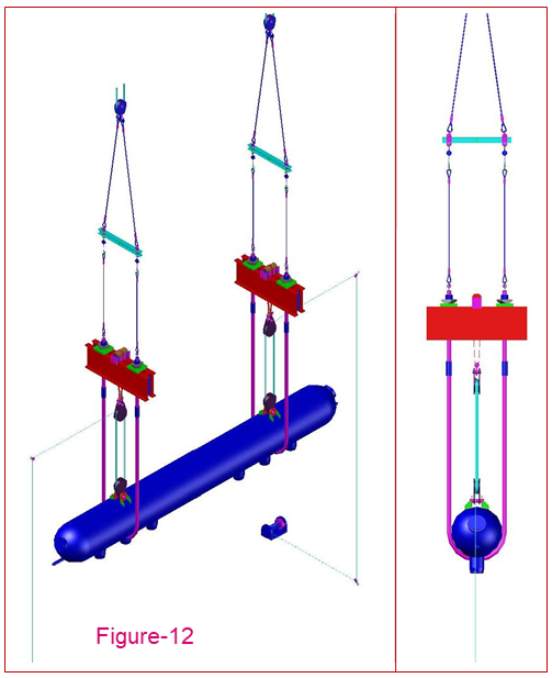
The length of steam drum is 16436 mm and the span between grid G2 and G4 at ELev. 46500 mm is 18000 mm. Therefore, the drum no needs to be tilted. The electric winch will be mounted on support. The movement and restraint will be by chain blocks. The electric winch will be operated from an electric current. The actual loads on electric winch as the drum are 7 ton, in actual load at pulley are 35 ton.
8.2. PREPARATION WORKS:
9. LIFTING PROCEDURE OF 72 ton BOILER DRUM
- Drum shall be delivered with center offset towards grid K1.
- Restrain the end of drum at grid K1 with chain blocks to prevent drum from hitting the column at grid K1 during its initial lift off.
- Lift the drum by approximately 100 mm and hold it for 15 minutes while all direct load bearing temporary and permanent girders and beams, winch system are checked for any undue deflections or connections (steel/hose) non conformities.
- Once the system has been cleared for safe lifting, the wood/steel/concrete blocks that are supporting the drum at ground floor are removed.
- Lift Winch 1 and Winch 2 by slowly.
- At this position, the drum shall clear the steel on both sides. A continuous monitoring on the condition of the lifting system shall be done. The watchmen shall continuous follow the drum while on its way up to check for any obstruction along the way of the drum. If there is any obstruction the watchmen will inform the lifting controller to hold the lifting until the obstruction is cleared, then resume lifting.
- Lift both ends together until the highest end is clear - above the Elev. 46500 mm.
- Lift the drum until U-Bolt connection can be made.
- After U-Bolt installation is complete, transfer the load from the lifting cables to the bolts.
- The lifting device shall be dismantled together with the temporary support to clear the way for erection work to progress.
10. LIFTING TOOLS
- Electric Winch capacities 10 ton : 2 unit.
- Tackle Block capacities 50 ton : 4 unit
- Rolling Block capacities 15 ton : 6 unit
- Rolling Block capacities 5 ton : 1 unit
- Shackle Omega capacities 50 ton : 2 unit
- Chain Block capacities 10 ton : 2 unit
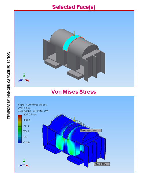
- Temporary Hanger capacities 50 ton : 2 unit
- Sling 22 mm 500 meter : 2 unit
- Wire Clip 7/8 inch : 6 pcs
11. RIGGING ANALYSIS
11.1.
Winch
Base-mounted
winches, or tuggers, are a compact, versatile tool for many hoisting and
pulling operations. They are particularly useful in areas not accessible to
mobile cranes or where there is not enough headroom for a crane to operate.
Figure 1 shows a tugger and snatch block arrangement for hoisting. Make sure
that the rope leaves the drum at a downward angle and that the loose end is
securely anchored.
11.2. Load Distribution

Figure 1
- Load of Steam Drum 72 ton
- Accessories 8 ton
- Total Load 80 ton
Load Distribution Every Point:
11.3.
Anchorage
Points
Hoists,
winches, tirfors, and other rigging devices require secure anchorage points.
Anchors may be overhead, in the floor, or at lateral points in walls or other
structures. The arrangement may involve columns, beams, beam clamps, welded
lugs, slings, or block and tackle. Whatever the method, riggers must be certain
of the loads involved and the anchorage required.

- Lead Line Load = ( Load)/(Parts of Line at Load)
- Lead Line Load = ( 40 ton)/(6 line)=6,667 ton ~ 7 ton
- Load on structure = Load + Lead Line Load
- Load on structure = 40 ton + 7 ton = 47 ton
11.4. Safety Factor of Sling

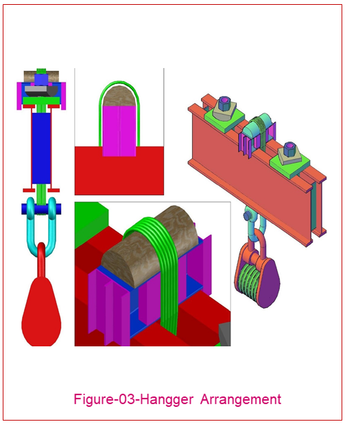


12. LIFTING ARRANGEMENT


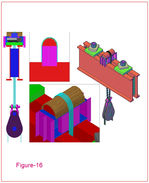
14. U BOLT HANGER INSTALLING

Preparation for U bolts arrangement.


Connect U Bolt to Sling (lifting tools).
Steam Drum at elevation +47750 mm.

Lift U Bolt until true elevation by slowly.
Adjust top of U bolt elevation by chain block.
After U bolt in true position, steam drum is degrading by slowly to true position on U bolt.


U bolt install and rigging arrangement for lifting.